Elementary comparison testing
Elementary comparison testing (ECT) is a formal white-box, control-flow, test-design method.[1] Its purpose is to implement the detailed testing of complex and important software. Software pseudocode or code is tested to assess the proper handling of all decision outcomes. As with multiple-condition coverage[2] and basis path testing,[1] coverage of all independent isolated condition paths is accomplished through modified condition/decision coverage (MC/DC).[3] Isolated conditions are aggregated into connected situations creating test cases. The independence of a condition is shown by changing the condition value in isolation. Each relevant condition value is covered by test cases.
A test case
A test case consists of a logical path from start to end of a process, through one or many decisions. Contradictory situations are deduced from the test case matrix and excluded. The MC/DC approach isolates every condition, neglecting all possible subpath combinations and path coverage.[1]

where
- T is the number of test cases per decision, and
- n the number of conditions.
The decision consists of a combination of elementary conditions


;


The transition function is defined as

Given the transition


the isolated test path consists of


Test case graph
A test case graph illustrates all the necessary independent paths (test cases) to cover all isolated conditions. Conditions are represented by nodes and condition values (situations) by edges. All program situations are addressed by an edge. Each situation is connected to one preceding and successive condition. Test cases might overlap due to isolated conditions.
Inductive proof of number of condition paths
The elementary comparison testing method can be used to determine the number of condition paths by inductive proof.
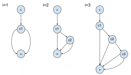
There are possible condition value combinations
.
When each condition is isolated, the number of required test cases per decision is:


there are edges from parent nodes and edges to child nodes from .


Each individual condition connects to at least one path

from the maximal possible connecting to isolating .


All predecessor conditions and respective paths are isolated. Therefore, when one node (condition) is added, the total number of paths, and required test cases, from start to finish increases by:


Test-case design steps
- Identify decisions
- Determine test situations per decision point (Modified Condition / Decision Coverage)
- Create logical test-case matrix
- Create physical test-case matrix
Example
This example shows ETC applied to a holiday booking system. The discount system offers reduced-price vacations. The offered discounts are for members or for expensive vacations, for moderate vacations with workday departures, and otherwise. The example shows the creation of logical and physical test cases for all isolated conditions.


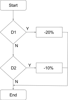
Pseudocode
if days > 15 or price > 1000 or member then
    return −0.2
else if (days > 8 and days ≤ 15 or price ≥ 500 and price ≤ 1000) and workday then
    return −0.1
else
    return 0.0
Factors
- Number of days:
- Price (euros):
- Membership card: none; silver; gold; platinum
- Departure date: workday; weekend; holiday


possible combinations (test cases).

Step 1: Decisions
| Outcome | |||||||
|---|---|---|---|---|---|---|---|
| Decision D1 | 1 | 0 | |||||
| Conditions | c1 | c2 | c3 | c1 | c2 | c3 | |
| c1 | 1 | 0 | 0 | 0 | 0 | 0 | |
| c2 | 0 | 1 | 0 | ||||
| c3 | 0 | 0 | 1 | ||||


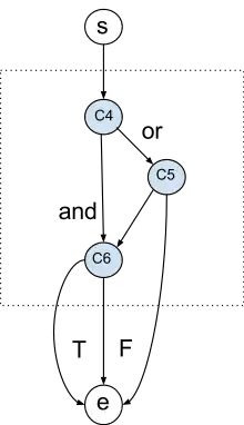
Step 2: MC/DC Matrix
| Outcome | |||||||
|---|---|---|---|---|---|---|---|
| Decision D2 | 1 | 0 | |||||
| Conditions | c4 | c5 | c6 | c4 | c5 | c6 | |
| c4 | 1 | 0 | 1 | 0 | 0 | 1 | |
| c5 | 0 | 1 | 1 | ||||
| c6 | 1 | 0 | 0 | ||||


The highlighted diagonals in the MC/DC Matrix are describing the isolated conditions:
all duplicate situations are regarded as proven and removed.

Step 3: Logical test-Case matrix
| Situation | |||||||
|---|---|---|---|---|---|---|---|
| x | |||||||
| x | x | x | x | ||||
| x | |||||||
| x | |||||||
| x | |||||||
| x | |||||||
| x | |||||||
| x |


Test cases are formed by tracing decision paths. For every decision a succeeding and preceding subpath is searched until every connected path has a start and an end :


Step 4: Physical test-case matrix
| Factor\Test Case | |||||||
|---|---|---|---|---|---|---|---|
| days | 16 | 14 | 8 | 8 | 8 | ||
| price | 1100 | 600 | |||||
| departure | sa | ||||||
| member | silver | ||||||
| Result | |||||||
| 0 | 0 | ||||||
| -10 | 1 | 1 | 1 | ||||
| -20 | 1 | 1 | 1 | ||||
Physical test cases are created from logical test cases by filling in actual value representations and their respective results.
Test-case graph
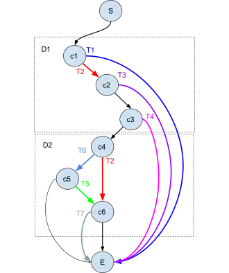
In the example test case graph, all test cases and their isolated conditions are marked by colors and the remaining paths are implicitly passed.
References
- Lee Copeland (2004). A Practitioners Guide to Software Test Design, chapter 10. Artech House Publishers, Norwood. ISBN 0140289712.
- Glenford J. Myers (2004). The Art of Software Testing, Second Edition, p. 40., John Wiley & Sons, New Jersey. ISBN 0-471-46912-2.
- Tim Kroom (2006). TMap Next, for result driven testing, p. 668. UTN Publishers, Rotterdam. ASIN B01K3PXI5U.